Share
Results 1 to 19 of 19

Thread: Cracked right in the middle of the aluminum weld

  1. Default Cracked right in the middle of the aluminum weld

    I was wondering if some of you guys could offer some advice on my set up.

    I made a custom aluminum plenum for my race car. Everything was TIG welded and I just used the filler rod that the guy at the LWS gave me (don't remember).

    Anyways, The plenum is very wide so it would bulge out under boost pressure and then suck back in from vacuum when the throttle plate was closed. This caused an "oil can" effect which eventually cracked my weld right down the middle of the bead.

    I have since reinforced the top of the intake manifold to keep it from flexing under boost and vacuum. However, I am wondering if the weld was just not as strong as it could be. Mainly because I watched the video online of the guy who OXY welded two aluminum sheets together using flux (obviously). He then proceeded to beat the piss out of it, shape it, smash it, stretch it and then shrink it. He abused this thing for a while and the weld never gave. So I am thinking my weld was inadequate since it cracked from just a little oil canning of the plenum.

    What do you guys think? Unfortunately I don't know the grade of aluminum that was used as the brake metal or the filler rod I used (I think 4043 rod). Maybe a particular filler rod would be better? I don't think it is a matter of penetration due to the fact that it split right in the middle of the weld right?

    I just don't know. Maybe the answer is simply reinforcing the top like I did to keep it from flexing. It has held up fine ever since then, but it is still something I think about.

    Here is the weld.

    Here is a picture of the plenum before I reinforced it. Lots of surface area allowing the top to flex a bunch.
    10.3 @ 134mph 1.5 60' DA 7500ft Bandimere speedway
    http://www.youtube.com/watch?v=leUB4PCv0mU

    Lincoln PT185
    1980's Miller Plasma cutter
    Everlast LX225 here and working well.

  2. #2

    Default

    Rapid cooling can do it...Also just leaving a crater or finishing off a weld suddenly can cause it to crack (Good reason for long downslope).
    Base alloy content can influence it as well.

  3. #3

    Default

    If the plenum is that large and you don't have it reinforced, it will probably crack everytime, unless you made it out of 3/16 thick sheet or similar. The area of a panel of the plenum (in²)multiplied by the boost pressure (psi) will give you the force just on one panel. Couple that with teh bending stress because the weld is at a corner adn you have huge stress in the weld. I have seen a few plenums split at higher boost levels.
    Everlast 200DX
    Everlast PT185
    Shoptask 3-in-1 (not currently in my garage, but I own it...)

    Any day on a motorcycle like this that ends just needing parts and labor is a good day.
    4.82, 158.67mph 1/8th mile 7.350, 200.35mph 1/4 mile

  4. Default

    Quote Originally Posted by sportbike View Post
    If the plenum is that large and you don't have it reinforced, it will probably crack everytime, unless you made it out of 3/16 thick sheet or similar. The area of a panel of the plenum (in²)multiplied by the boost pressure (psi) will give you the force just on one panel. Couple that with teh bending stress because the weld is at a corner adn you have huge stress in the weld. I have seen a few plenums split at higher boost levels.

    The way I reinforced it was... I welded two plates about 5" X 5" X 3/16" thick to the top of the plenum making it a total of 5/16" thick on top. As I said, this eliminated flexing and I have not had a problem since.

    So that is probably about the only thing to keep that from cracking is keeping it from flexing huh?
    10.3 @ 134mph 1.5 60' DA 7500ft Bandimere speedway
    http://www.youtube.com/watch?v=leUB4PCv0mU

    Lincoln PT185
    1980's Miller Plasma cutter
    Everlast LX225 here and working well.

  5. Default

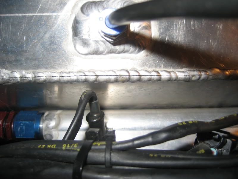
    The engine pod on my Bennington pontoon boat did this. It was a four foot long weld. It started as a 1 inch crack, and worked it's way across the transom in a day. No undo stresses, the unit is 4 feet wide and 80 inches long, welded all the way around so it wasn't a significant portion of anything special. EXCEPT; we were pulling a skier [we have 100's of hours of this before] I think once we got that little crack that the pulling/tear force is what caused ours, similar to having something improperly torqued. It may be a product of a torque sequence more than the pressure put upon it by the intake air.

    As an aside; Local welders were stumped. Bennington put it on a trailer and took it from AZ to Indiana, put on a whole new pod, then shipped it back to me. The boat was 8 years old, and they were still good for the warranty.

    Just sayin' you might have a little lateral twist thing going on. I think the lateral would search out a weld to screw with since it is a straight line that is 'regrained' from the rest of the material.
    I am out trying to 'find myself'. If I should wander back while I am gone, please tell me to sit quietly and wait for myself to return.

    LOTS of scuba and vintage scuba equipment [I'm Always willing to trade or buy the stuff you think is too old to use]
    Smithy XLT Mill/lathe [It was easier to learn than I thought, I'm no pro, but I can make a bearing hanger]
    Everlast PP256

  6. #6
    Join Date
    Dec 2009
    Location
    Greater Seattle, WA
    Posts
    813

    Default

    The welded joint was obviously weak (lacking strength) and brittle (lacking ductility) compared to the rest of the structure. Otherwise the structure would have failed by "ballooning" out from excessive pressure, (at least a little bit,) while the weld joint would have kept on holding.

    Most obvious explanation is inadequate weld joint penetration. But there are a couple other potential contributing factors...

    * inadequate penetration. Ideal way to "fix" this would be by welding the front and back sides of the joint, instead of only welding one side of the joint. If welding only one side, you could test your penetration and weld joint strength on some test coupons first (by bending them in a vice until failure), taking notes on the force it took to bend and fail, also observe the penetration obtained in the fracture pattern. Then make any changes as necessary to improve your penetration (IE: adjust current, travel speed, etc).
    * improper filler rod selection (producing a weld bead lacking strength and ductility) Could be fixed by knowing your Parent metals, and then consulting the Alcoa filler rod selection for aluminum chart to select a good rod. Don't just grab and use whatever filler rod is convenient.
    Link to Alcotec filler rod selection chart
    * inadequate puddle dilution by the filler rod (for crack sensitive alloys, like 6061). The fix is configuring the weld joint to give a space for the filler rod to flow into, like setting up an open corner joint instead of closed corner. Or beveling the edges of a butt joint.
    Last edited by jakeru; 03-19-2011 at 05:44 AM.
    '13 Everlast 255EXT
    '07 Everlast Super200P

  7. #7

    Default

    I'd like to see the other end of that bead where the crack began. Did the crack start at the beginning of the weld or the end of the weld? I'm not the welder jake is, but this has ahppened to me before. To my humble eyes, it looks like Lack of penetration and or improper crater fill. I learned pretty quick that the downslope feature is my friend here, and to keep the last dip shielded for maybe ten seconds or so. Some guys say fifteen. Like mark said, slow downslope and post flow.
    Everlast PP256
    Everlast Imig 205
    HF 90 am inverter tig
    Scopes, Scanners, Meters

  8. #8

    Default

    If you made a simple fillet weld with the to pieces mated inside edge to inside edge, the center of the weld could have been very thin, if there was incomplete penetration and not enough filler was used.

  9. #9
    Join Date
    Mar 2011
    Location
    mission viejo CA
    Posts
    92

    Default

    I would say it was caused by lack of fusion at the root of the weld and cracked from the inside out from it flexing
    Lincoln precision tig 275
    Miller Syncrowave 350 Tig
    Miller 250 Mig
    old miller 200 Mig
    HF 151 Mig
    HF 100 FC
    Victor Journeyman Oxy/Ace set up
    Bunch of tools of the trade to much to list

  10. Default

    Quote Originally Posted by performance View Post
    If you made a simple fillet weld with the to pieces mated inside edge to inside edge, the center of the weld could have been very thin, if there was incomplete penetration and not enough filler was used.
    With some thicker material this would be a good idea.

    Your weld lacks penetration. You have managed to only create a bead on the surface. probably using the corner of each piece of metal as filler. Just to note your bung weld is too hot and not enough filler. You need to slowly end the weld and add filler at the very end so you don't leave craters, which are basically a crack.

    Make sure to scotch brite the metal inside the joint as well. A wipe with acetone is also a good idea. When I built AL bike frames, we had a scotch brite type of abrasive wheel to clean up the weld area and then dipped it into an acetone container. The cleaner you get the weld and keep your gloves/work area the cleaner the weld will be - that part is up to you.
    Alternatively you could make this into a lap joing by putting a 90 on the side piece so the top would sit right on top.
    Last edited by froader; 03-19-2011 at 11:20 PM.

  11. #11
    Join Date
    Feb 2011
    Location
    Mountain Home Arkansas
    Posts
    46

    Default

    Not that I am suggesting that you redesign the whole thing but. If you rolled the sides and relocated the welds to the side and not in a corner and also put a few bead roll profiles in it, really helps to stiffen it up. It will relieve some of the stress on the welds. I have some pics of one I made some years ago, I will try to find them and scan them into the computer and post them.

    SHOP SETUP
    Esab Migmaster 250
    Everlast PowerPlasma 50
    Miller Dynasty 200 DX TIG
    CNC Express SQ Mill
    CNC Lathe 1236
    Plate Shear 12"
    12" Slip Roll
    4 Ton Notcher
    4 Ton Hand Punch
    52" 18 Gauge Foot Shear
    48" Pan & Box Brake
    Spot Welder
    50" Slip Roll
    English Wheel
    Bead Roller
    Planishing Hammer
    60" Hand Brake
    7" x 12" Bandsaw
    Hand Tools
    Shop (TOO SMALL !!!!! )
    I don't owe anyone a dime, but I get paid to lay them down

  12. Default

    I dont see any evidence of lack of penetration, certainly not without looking at a cross section of the weld. If the intake is flexing as you say than there is definately a "structural" issue you need to consider. ANY part or structure subjected to repeated cycles of dynamic displacement will fatigue ...... eventually. So that is something that needs to be accounted for by design. In this case the most obvious would be to stiffen the walls by some means, as you have done, and that alone may dodge the bullet for some time. As was mentioned many ways to skin that cat. BUT ... that being said, IMHO the crack along that weld does not look like a fatigue crack due to flexion. Those tend to be more jagged, .... not so clean and down the center. This looks more like a "crack waiting to happen" or one that may have started almost immediately even if nearly imperceptable. This looks to me more likely a base material issue ( and or ) a heating / cooling issue. It really looks a lot like improperly handled 6061-T6, which is super crack prone right down the center lane if ya don't do it like it likes to be done. 6061 can be really bitchy if your trying to just knock out a fab on something. Other alloys too, .... so i don't know what base metal ur using but in general 4043 filler rod is a good choice if you dont know, and is a softer more malleable alloy, which is why it's good for castings which experience a lot of expansion and contraction.

    The GAS welding demo and insuent pounding and shaping of the aluminum coupons is expected as that process produces a more generalized heating, or in other words a slower larger heat affected zone. That makes for more of an ANNEALED piece to work with and is soft and malleable. Such is the science of design, ..... it is not stronger, but it is more flexible. Strength is defined by requirements of the design.

  13. #13

    Default

    Quote Originally Posted by trackmaster View Post
    ...This looks to me more likely a base material issue ( and or ) a heating / cooling issue. It really looks a lot like improperly handled 6061-T6, which is super crack prone right down the center lane if ya don't do it like it likes to be done. 6061 can be really bitchy if your trying to just knock out a fab on something. Other alloys too, .... so i don't know what base metal ur using but in general 4043 filler rod is a good choice if you dont know, and is a softer more malleable alloy, which is why it's good for castings which experience a lot of expansion and contraction...
    That is what I was thinking too...
    __________________________
    Everlast Power I-MIG 200
    Everlast PowerUltra 205P
    Everlast SM 200-N
    Thermal Dynamics Cutmaster 42

  14. #14

    Default

    This happened to me also, I had a good fit up, so I tried to tig it without filler rod. It didn't work, cracked down the middle. Did the same weld with 4043 rod and the weld turned out decent. 6061 will loose it's strength next to the weld where it was hot, watch for that too. Jodi from Welding tips and tricks recently put out a very quality video about this.
    James Swanson

    Millermatic 135
    (saving for a Power pro 256)
    Linde HDA200
    Custom water cooler and cart

  15. #15

    Default

    Gerald

    Millermatic 251
    Spectrum 300 Plasma
    Everlast PowerTig 250EX
    Everlast PowerCool W300
    Harris / Victor OA
    Craftsman 13 Speed Drill Press
    ProTools Air/Hydraulic Bender
    48" Brake, 72" Brake, 52" Stomp Shear
    Mitler Bros. 36" High Throat Bead Roller
    Compressor, Notchers, Grinders, etc.

  16. Default

    Unfortunately, the picture proves that the weld is the weakest part of the whole joint - it cracked right down the middle.
    If you have a correct bead, any cracks would have developed in the HAZ(heat affected zone). This is right on the edge of the weld.
    This is a penetration issue, which can be solved with prepping the joint correctly, using the correct amount of power and laying a correct bead. Just practice on some scrap in the same fashion first.
    Last edited by froader; 03-24-2011 at 04:50 PM.

  17. Default

    Quote Originally Posted by froader View Post
    Unfortunately, the picture proves that the weld is the weakest part of the whole joint - it cracked right down the middle.
    If you have a correct bead, any cracks would have developed in the HAZ(heat affected zone). This is right on the edge of the weld.
    This is a penetration issue, which can be solved with prepping the joint correctly, using the correct amount of power and laying a correct bead. Just practice on some scrap in the same fashion first.
    LOL, This is correct. I have been out practicing putting more heat into it. My weld would not melt together on the back side of the weld typically. It would always be two separate blobs down the length of the weld with a split right in the middle. I have been out there melting some practice pieces together to get it to melt all the way on the back side now. Think I've got it down now.

    On a side note, the design should be where the top of the intake should not flex regardless.

    Thanks for the input guys.
    10.3 @ 134mph 1.5 60' DA 7500ft Bandimere speedway
    http://www.youtube.com/watch?v=leUB4PCv0mU

    Lincoln PT185
    1980's Miller Plasma cutter
    Everlast LX225 here and working well.

  18. #18

    Default

    how long after you put it together did it crack?
    sold my miller mig
    got a PT250EX
    saving up for a plasma cutter

  19. Default

    It was probably a month of driving it around with both boost and vacuum.
    10.3 @ 134mph 1.5 60' DA 7500ft Bandimere speedway
    http://www.youtube.com/watch?v=leUB4PCv0mU

    Lincoln PT185
    1980's Miller Plasma cutter
    Everlast LX225 here and working well.

Similar Threads

  1. 250DX AC Aluminum Weld Issue
    By dmost in forum TIG Welding (GTAW/GTAW-P)
    Replies: 58
    Last Post: 11-30-2013, 08:04 PM
  2. How to weld TALL weld beads on 1.6mm thick Aluminum Tube?
    By Welderooni in forum TIG Welding (GTAW/GTAW-P)
    Replies: 4
    Last Post: 10-08-2013, 02:49 PM
  3. Vertical Up Tig Weld W/185 Micro on 11 Ga Aluminum
    By cbmkr in forum TIG Welding (GTAW/GTAW-P)
    Replies: 1
    Last Post: 10-28-2012, 05:02 PM
  4. Oxy/Ac weld aluminum for a horse stand
    By beezfun in forum General Welding Questions
    Replies: 7
    Last Post: 08-28-2011, 09:27 PM
  5. how thin of aluminum can we weld
    By www in forum Multi-Process Units (TIG,Stick,Plasma/MIG,TIG,Stick Combo units)
    Replies: 9
    Last Post: 07-21-2010, 10:06 PM

Posting Permissions

  • You may not post new threads
  • You may not post replies
  • You may not post attachments
  • You may not edit your posts
  •