Share
Results 1 to 13 of 13

Thread: DIY : How to make your own durable,cost effective and low profile foot pedal\control.

  1. Default DIY : How to make your own durable,cost effective and low profile foot pedal\control.

    Hello again and today I will be showing you how to make your very own foot pedal for your Tig welder.The only part you will need from your existing foot pedal is the cable with the 7 pin connector that attaches to your welder.Please note I am covering the 47k ohms foot pedal which is found on the PowerTig 200DX and any other pedals that uses a 47k ohms potentiometer.The total cost can be any where from $50 to $90 depending on where you source the parts.

    Parts needed:
    Qty (1) Vox 845 black power coated or 847 chrome foot pedal (you can find them on eBay from $45 to $70)
    Qty (1) SPDT - momentary push button switch for $4.50 http://www.ebay.com/itm/370820332929...84.m1439.l2649
    Qty (1) 3/8 Rubber grommet pack of 10 for $8.00 http://www.ebay.com/itm/BB24-PK-of-1...c65cb4&vxp=mtr
    Qty (3) 90 deg Torsion springs http://www.mcmaster.com part# 9271K56 pack of 6 for $7.79
    Qty (2) 100k resistors pack of 5 for $2.00 or Qty (1) 50k ohms potentiometer $8.00

    Parts Optional:
    Aluminum foil tape (to help keep the dust out)
    Shrink wrap sleeves (to keep the wires organized)
    1/4'" Nylon cable clamps (to keep the wires down)

    Tools needed:
    Solder iron and wire
    #2 Philips screw driver
    Pliers or wire cutter
    Drill and bits 1/4 and 1/2
    Small punch and hammer
    Silicone grease or any other thats available

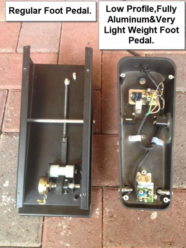
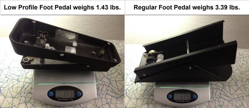
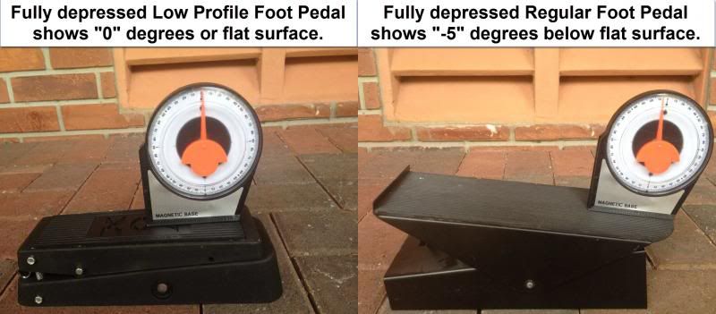
    I also want to mention that the reason I chose the VOX pedal is because its very durable,light weight and low profile.The rack & pinion design makes it great for precision and control.

    Step 1:
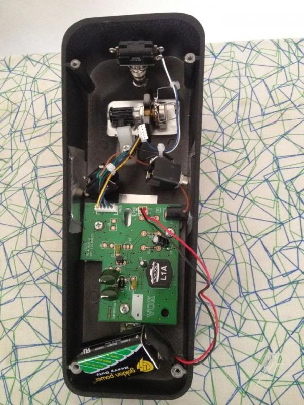
    Open the VOX foot pedal by unscrewing the 4 screws located under the foot pedal.Remove the circuit board,wires,switch and (optional) head phone female jacks.

    Step 2:
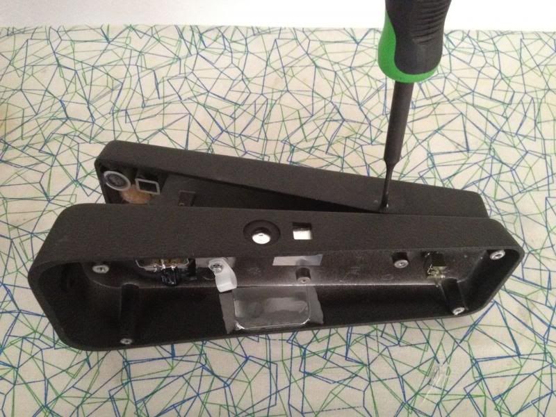
    Use the pliers to remove the 2 nuts and bolts that is holding the shaft down.Then use the punch and hammer to remove the shaft and to separate the 2 halves Please note that the shaft goes in and out one way so mark one side and place the punch on the pointed side of the shaft not the flat side.

    Step 3:
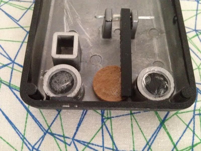
    Remove the 2 round rubber cushions from the top half of the pedal.I already removed them in this picture but you can still see a little black residue from them.Doing this will give the foot pedal 100% travel from 0k ohm to 50k ohms.

    Step 4:
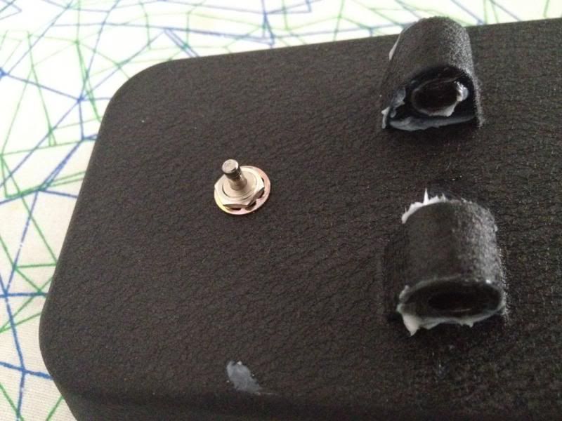
    Installing the SPDT switch is very easy,there is already a small hole at the base of the bottom half of the pedal from when you removed the nut and bolt.Just use the 1/4" drill bit and widen the hole then install the switch and lock it in place with the lock nut.

    Step 5:
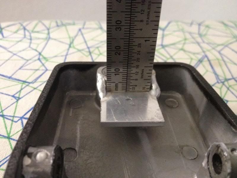
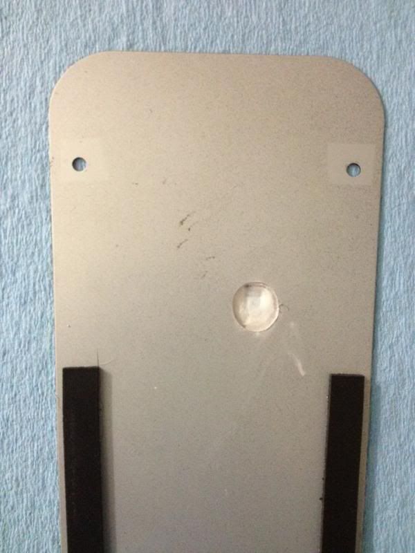
    Next is welding a small piece of aluminum on the top half of the pedal to active the switch.I used a 1/8" thick aluminum bracket and 5mm from the bracket to the top is perfect.Remember to remove the rubber cushion before welding and try not to weld for too long just 2 tacks is good enough.

    Step 6:
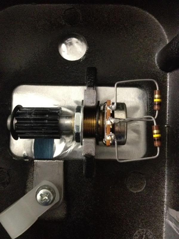
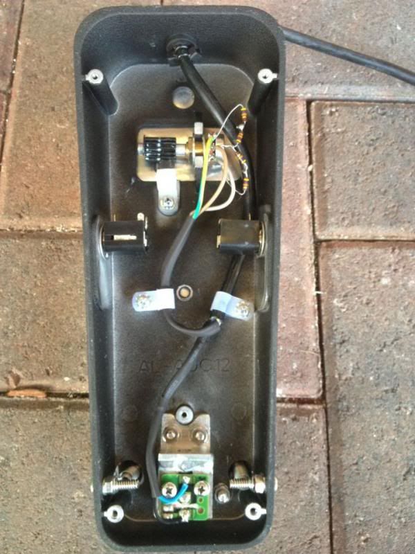
    Take the (2) 100K resistors and solder them just as shown in the picture,doing this will give you linear control by cutting down the original potentiometer that was 100k ohms to now 50k ohms Or you can install your own potentiometer with the correct value.

    Step 7:
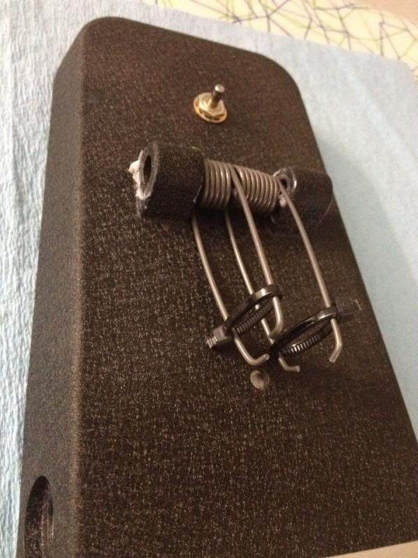
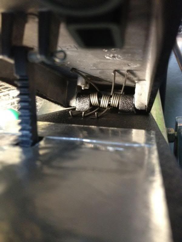
    Its now time to reassemble the pedal but before you do that the torsion springs have to be compressed.So follow exactly as shown in the picture using zip ties and reinstall the shaft,Wear safety glasses.


    Step 8:
    After assembly drill a 1/2" hole at the front and install the rubber grommet and document the cable pin outs and remove it from your old pedal then push it through the grommet.
    Step 9:
    Adjust the rack & pinion in the correct position and install the base, mark the spot where the rack is making contact then drill a 1/2" hole and re check for proper clearance.

    Step 10:
    Solder the wires to their correct locations ,reinstall the base screws.Your foot pedal should look like this when you are done.
  2. Default

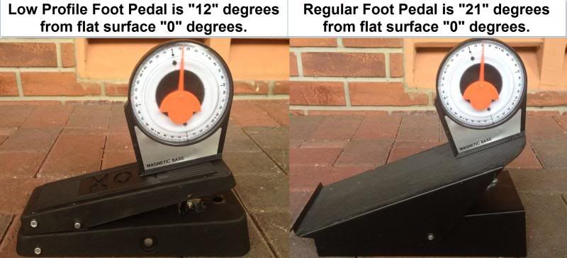
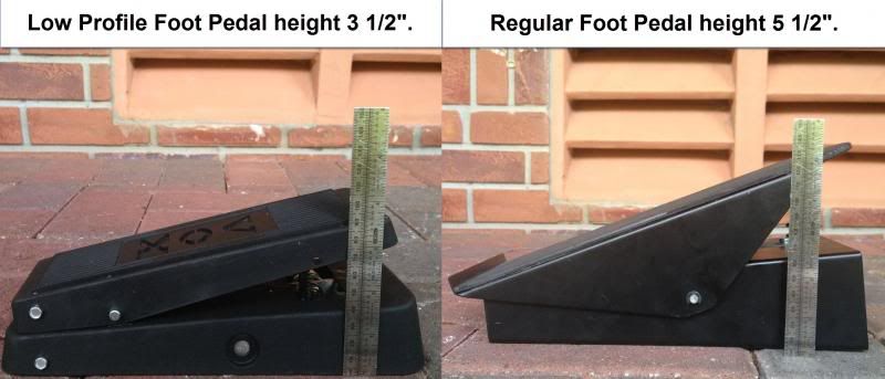
    Specs on both OEM and VOX.


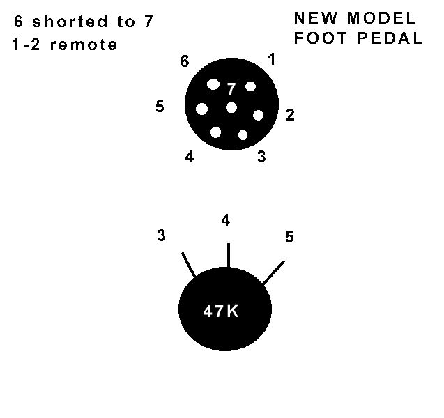
    Everlast PowerTig 200DX pinouts which I found in the threads.


    As a side note I have a extra pedal that I used to document this DIY ,so if anyone is interested PM me please I am just asking for what I paid in parts thanks.
    Last edited by watercooler; 07-22-2013 at 01:18 AM.

  3. #3
    Join Date
    May 2012
    Location
    Disneyland
    Posts
    2,662

    Default

    That really isn't the way to wire the resistors for a voltage divider type circuit. If you measure your pot from end to end you will find it is 66K ohm instead of the 50K you seek. While it is probably close enough, it doesn't help the resolution of your pot. Combined with the reduced mechanical travel and it will be a lot more twitchy to small foot movements. Just for info as depending on what you are welding and your work area it might just what you want. Also there are two types of pots commonly made. One is linear taper (B) and with show half value and half travel, the other is audio taper (A) and will show an approximate logarithmic scale. Since you started with a piece of audio gear, you might have the later, but again that might be a plus or a minus depending on what you are looking for.
    Long arc, short arc, heliarc and in-the-dark!

  4. #4

    Default

    A wonderful project,,,well done and well thought out,,,,however it requires sources and skills that aren't available to most people,,,add to that the limited building skills that we all have,,,,and ,, it becomes obivious that if we want a low profile pedal,,then we will end up buying one from some supplier,,,not to say that your build is not good,,,it is good,,,just beyond my skills and time available for such a change..nice post..for those that want to build their own low profile pedal..
    Some of those lies people tell about me, are true

  5. #5
    Join Date
    May 2012
    Location
    Disneyland
    Posts
    2,662

    Default

    Quote Originally Posted by geezer View Post
    ...however it requires sources and skills that aren't available to most people..
    I would think a little welding and soldering is probably within the realm of anyone that frequents this forum. And with a slightly different switch, you can probably eliminate the aluminum welding for those that have DC only machines.
    Long arc, short arc, heliarc and in-the-dark!

  6. Default

    Quote Originally Posted by Rambozo View Post
    That really isn't the way to wire the resistors for a voltage divider type circuit. If you measure your pot from end to end you will find it is 66K ohm instead of the 50K you seek. While it is probably close enough, it doesn't help the resolution of your pot. Combined with the reduced mechanical travel and it will be a lot more twitchy to small foot movements. Just for info as depending on what you are welding and your work area it might just what you want. Also there are two types of pots commonly made. One is linear taper (B) and with show half value and half travel, the other is audio taper (A) and will show an approximate logarithmic scale. Since you started with a piece of audio gear, you might have the later, but again that might be a plus or a minus depending on what you are looking for.
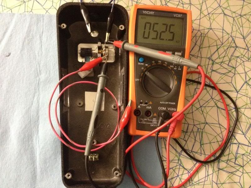
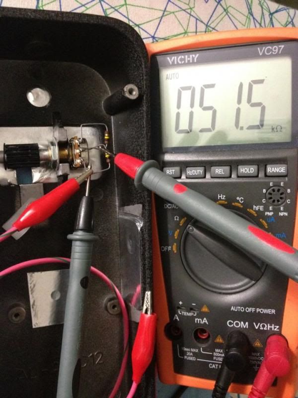
    That is incorrect,this method will give the pot full linear coverage from point A (start) to B (end).I have been working on this for a couple weeks and done some research and tests and by far this is the best way to go about it.I have retaken more pictures for proof.
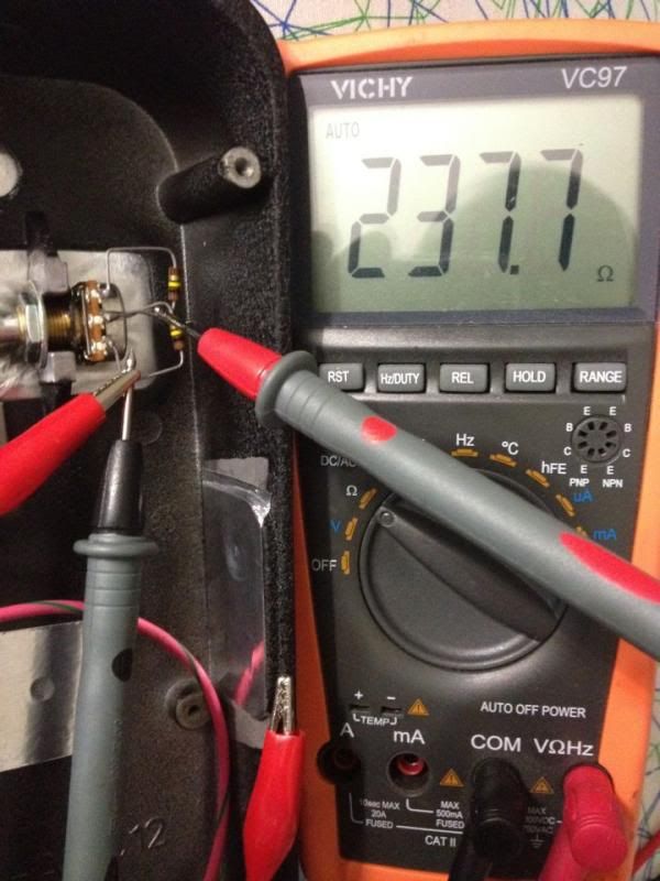
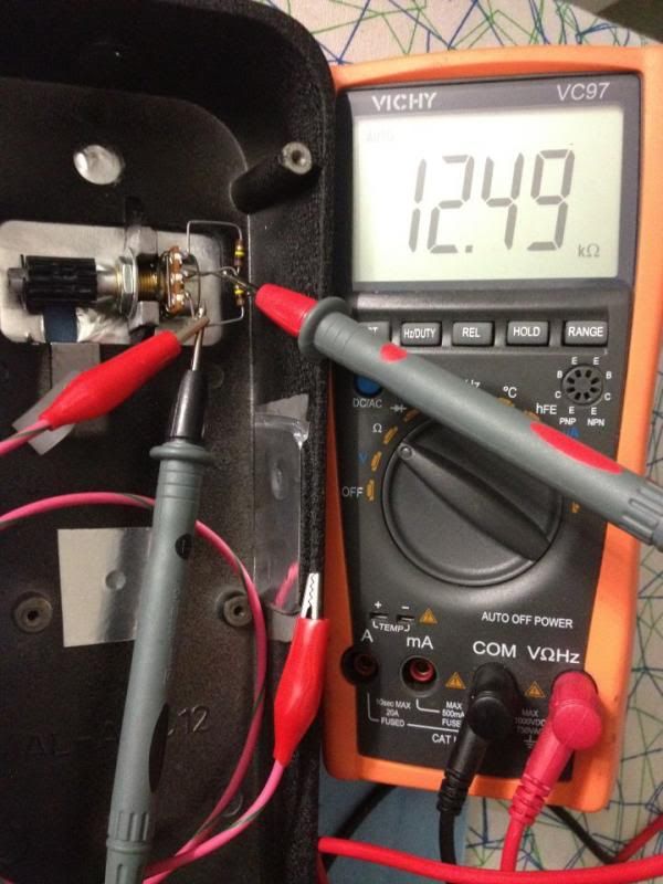
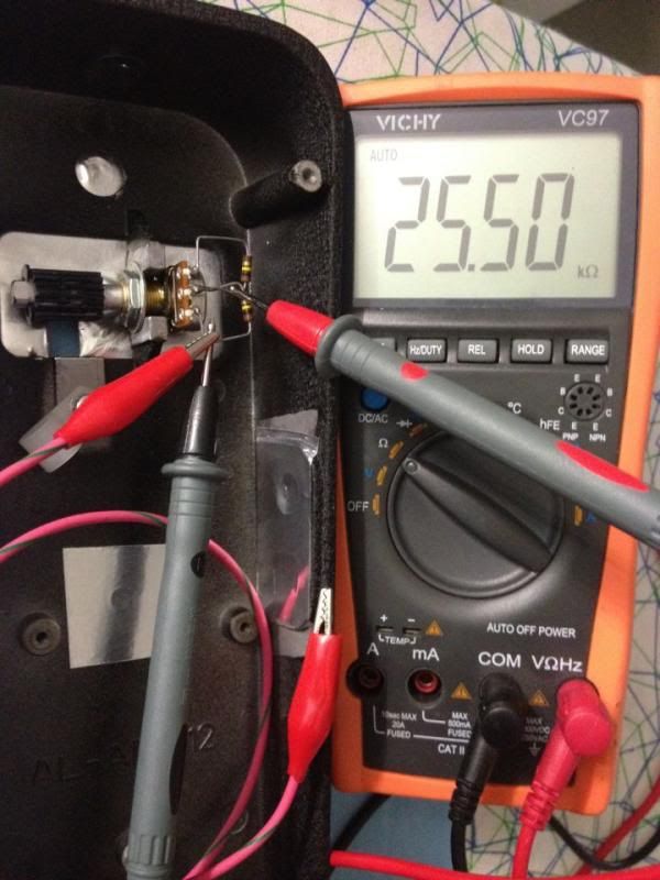
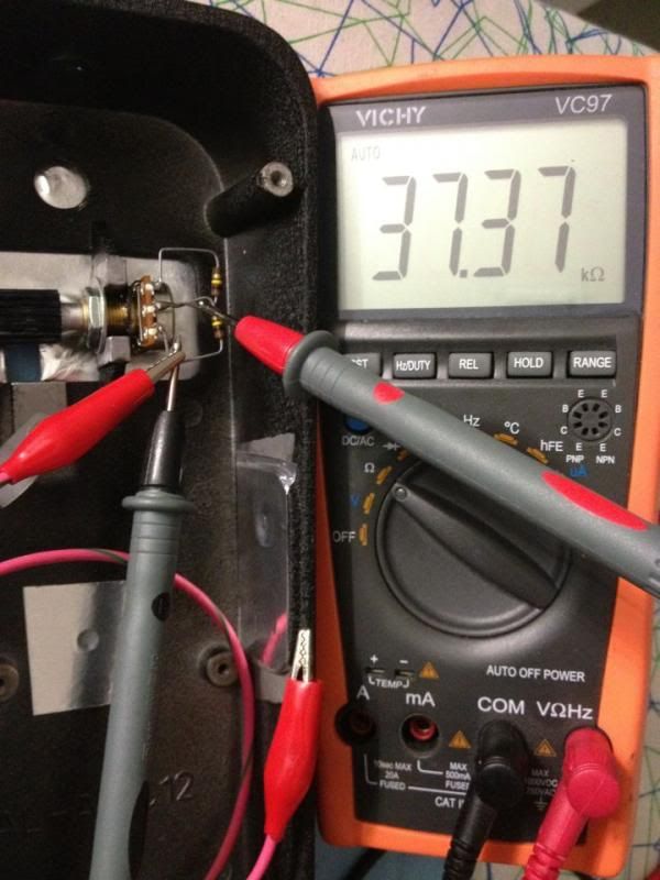
    The multi meter is connected parallel and shows 52k ohms which is in the 10% tolerance.

    This is at start position 0% showing 237 ohms.

    This is at next position 25% showing 12k ohms.

    This is at next position 50% showing 25k ohms.

    This is at next position 75% showing 37k ohms.

    This is at next position 100% showing 52k ohms.

  7. Default

    Quote Originally Posted by geezer View Post
    A wonderful project,,,well done and well thought out,,,,however it requires sources and skills that aren't available to most people,,,add to that the limited building skills that we all have,,,,and ,, it becomes obivious that if we want a low profile pedal,,then we will end up buying one from some supplier,,,not to say that your build is not good,,,it is good,,,just beyond my skills and time available for such a change..nice post..for those that want to build their own low profile pedal..
    Its a DIY and I understand that some people might not have any soldering skills but if we can tig weld (which is harder) I don't really see soldering 5 wires and making 2 tacks a issue.It will save you up to $100 but if this mod isn't for you then your option would be to buy one which is understood.

  8. Default

    Quote Originally Posted by Rambozo View Post
    I would think a little welding and soldering is probably within the realm of anyone that frequents this forum. And with a slightly different switch, you can probably eliminate the aluminum welding for those that have DC only machines.
    Correct Rambozo,there are many ways you can mount a switch that will accommodate your interest.The sky is the limit and your imagination is always free,just put it to logic and reap the rewards.

  9. #9
    Join Date
    May 2012
    Location
    Disneyland
    Posts
    2,662

    Default

    Maybe I wasn't clear. I'm not saying that it won't work, just that it has errors that you might have overlooked. There is actually no way to change one pot value to another without introducing errors of some type or another. The total impedance of your circuit will change with the position of the wiper. Again not by much, but in some circuits that would be a problem. As Mark mentioned in another post that this is a true voltage divider, the load you present to the reference voltage will vary slightly with wiper position. How it behaves with an ohm meter is not quite how it behaves in circuit under load. But you should be able to see the issue if you measure the resistance from the two outer terminals of the pot. That should be a constant, but the way you have it wired up there will probably be some changes as you rotate the pot. It will be correct at each end but drift high in the middle. Resistance is not really what this circuit uses for the adjustment anyway. What you are looking for is a smooth voltage transition from ground to the reference voltage. I believe Mark mentioned it was 5V, so in a totally linear system it would be 2.5V at mid travel. Again there are a lot of ways to play with this to get different types of voltage curves. But for a flat linear curve a single resistor will do better even though it won't seem that way when measured with an ohm meter. Of course ideally the best thing is to just use the right pot, or a close substitute.
    Long arc, short arc, heliarc and in-the-dark!

  10. #10

    Default

    Quote Originally Posted by Rambozo View Post
    I would think a little welding and soldering is probably within the realm of anyone that frequents this forum. And with a slightly different switch, you can probably eliminate the aluminum welding for those that have DC only machines.
    Well at my age,,buying green fruit is a gamble,,,so when it comes to a project like this i will have to go with a ready built..nice work and a well done project,,,just out of my list of projects..
    Some of those lies people tell about me, are true

  11. Default

    Quote Originally Posted by Rambozo View Post
    Maybe I wasn't clear. I'm not saying that it won't work, just that it has errors that you might have overlooked. There is actually no way to change one pot value to another without introducing errors of some type or another. The total impedance of your circuit will change with the position of the wiper. Again not by much, but in some circuits that would be a problem. As Mark mentioned in another post that this is a true voltage divider, the load you present to the reference voltage will vary slightly with wiper position. How it behaves with an ohm meter is not quite how it behaves in circuit under load. But you should be able to see the issue if you measure the resistance from the two outer terminals of the pot. That should be a constant, but the way you have it wired up there will probably be some changes as you rotate the pot. It will be correct at each end but drift high in the middle. Resistance is not really what this circuit uses for the adjustment anyway. What you are looking for is a smooth voltage transition from ground to the reference voltage. I believe Mark mentioned it was 5V, so in a totally linear system it would be 2.5V at mid travel. Again there are a lot of ways to play with this to get different types of voltage curves. But for a flat linear curve a single resistor will do better even though it won't seem that way when measured with an ohm meter. Of course ideally the best thing is to just use the right pot, or a close substitute.
    If thats the case then its better to just install the correct pot then.I got the information from this website and just remembered it said this at the bottom (The resulting value can fluctuate as the knob is turned. This may be a problem in certain DC applications.)http://www.diystompboxes.com/analogalchemy/emh/emh.html

  12. #12

    Default

    Nice little project for an adventurous DIY person. I've seen at least project where someone made a pedal from scratch!

  13. Default

    Yeah I have seen couple too but at least with this one majority of the work is done and all it takes is a few small mods and you will be on your way.Did I also mentioned that foot pedal pulsing is now a breeze due to the less effort you use with your foot.

Similar Threads

  1. Replies: 3
    Last Post: 06-19-2013, 04:21 AM
  2. Foot Control
    By kepp in forum Everlast Plasma Cutters (PAC)
    Replies: 12
    Last Post: 08-24-2012, 12:34 AM
  3. Power Pro 205 Foot Amp Control
    By scootarida1 in forum Multi-Process Units (TIG,Stick,Plasma/MIG,TIG,Stick Combo units)
    Replies: 6
    Last Post: 11-12-2011, 08:45 PM
  4. Low profile foot pedals...
    By rengaw21001 in forum General Welder Questions
    Replies: 0
    Last Post: 11-08-2010, 12:48 AM

Posting Permissions

  • You may not post new threads
  • You may not post replies
  • You may not post attachments
  • You may not edit your posts
  •