Share
Results 1 to 20 of 20

Thread: TIG pedal design and fab (may be overkill)

  1. Default TIG pedal design and fab (may be overkill)

    Hello, all...

    I'm glad to have found out after my purchase, that this forum is here and has contributions from Everlast representatives.

    My Powertig 185 machine came with a torch mounted trigger, so I don't currently have a pedal for my unit. I quickly discovered what a necessity this is, for pulse control on this machine and clean entry and exit on beads. It does rather well on thicker steel without pulsing the on/ off trigger, on cold metal, but after a while, with heat soak it's too much, ramps heat up quickly on the heated part and I have to stop welding.

    I was working on my cart/ storage drawer/ mock up table and decided to shift gears to build a pedal.

    I saw the youtube video on the modded guitar pedal. I like the idea of a rack and cog gear for linear control over the entire rotation of the pot. I don't like that the throw of the rack doubles the length needed for clearance, so a vertical rack increases the overall pedal height with unused space below, that it needs for clearance. I've seen cog and belt designs that incorporate pull springs that solve this clearance issue, but I'd like to minimize wear parts in the pedal.

    I was going to buy a low profile pedal, but I also thought that the rack idea could still be used in a low profile design, as well as consolidating functions and hoses strung across the floor.

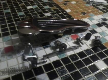
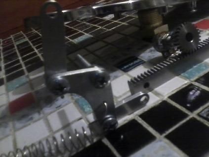
    So I took the rack idea and changed the design, so it fits horizontally, sliding forward and backward, beneath the cog/ potentiometer. I'm using a 90 degree arm that pivots at the elbow, like a kickdown linkage on an automatic transmission, to allow a vertical link at the toe of the pedal, to transmit to another link that moves horizontally (mostly), connected to the completely horizontal rack.

    I wanted to keep the remote trigger, for it's tac capabilities, especially under a car, lying on the ground, doing exhaust mockups or other placing tac welds that require positions.

    I've figured out how to incorporate automatically switching from trigger to pedal, without the use of a relay, by engaging a microswitch from the pedal's movement, before engaging the rack linkage. This will be done with a slotted hole somewhere on the linkage, between the rack and the pedal toe, so the motion of the pedal engages the micro switch first. The switch that I bought is a 1P2T type, so it is not on/ off, but rather on/ on. This means that I can run three wires to it, so I can have the hand trigger engaged when the pedal is up and the pedal trigger engaged when it's slightly pressed, before the pedal is on (another micro switch) and the potentiometer moves at all.

    I didn't feel like tossing my 15' cable that came with my welder, so instead of upgrading to a 25', I'm going to use the pedal as a junction box, to attach an additional 12' 6" CK Superflex hose. This will give me a total distance of about 28' distance with the pedal, but I figured that 12' will give me enough slack to reach, from the pedal, to any place I could want to reach and a little further, if I'm just out to tac something in mock up, so I can take it off for final welding with a pedal.

    The beauty of the 90 degree linkage arm, is that I can have inequal arm length on both ends of the L, so I can change pedal throw to rack throw ratio. Even though I can do this infinately with slotted holes and a locking nut, or multiple holes, I think I'm going to set it to a comfortable foot angle ratio. The rack and cog that I have are stainless and goes through a 2" rack throw, for 335 degrees of cog rotation from stop to stop. I'm going to use threaded rod for the link arms, so I can dial the adjustments in, as not to over or under throw the rack.

    Overall sensitivity on amps will be done with a second pot on the side of the pedal. I know I can get the ratio nice with the L linkage, but I actually want to be able to adjust sensitivity on the fly, because I work on a very wide range of metals and thicknesses on a regular basis.

    The one downfall to using the CK superflex, is that I lose a little of it's purpose on a torch mount trigger, having a 2 conductor wire running down the whip. So, I decided to purchase a wireless remote that runs a relay. The remote is a momentary on button that transmits a signal to the relay reciever. The range is really far and will work fine for what I want to do. This will also enable me to tac weld using my other hand, if I remove the trigger from the torch, and also allow me to remove the trigger when I'm not using the torch for tac welding, so I don't accidentally tac and for comfort. I will be attaching it with velcro strap.

    The set comes with two remotes, so I can keep one in my consumable drawer on the cart, in case the battery goes dead or one is damaged, etc.

    I thought about the HF start having a problem with radio transmission frequency, but the frequency of the device is much higher than the HF on the welder. HF is up around 2MHZ and the transmitter is at 340MHZ, so there is no way signal disruption will even come close in bands for the hand/ remote trigger.

    Having a 2nd remote also opens the possibility of having an aid help with difficult tacs for positioning, like a header build. I could have one in the trigger or my other hand and call out start/ stop while crawling under a car or something.

    So far, I've got the pedal, stainless sheet material for the pedal base, cog gear and rack, potentiometer (bought 50k and 25k ohm, gonna try both out) and the short rubber feet for the entire pedal to sit on. I'm waiting on the CK whip, 7 pin 5/8" connector, wireless remote and 12v receiver relay. I've decided to tackle power to the relay with a 12v battery, either special order or with a 9V and 2 AA 1.5v units.

    I could run power to the relay in the pedal for the wireless trigger, from the power lead on the welder.

    What gauge of wire is suitable for the 7 leads and what is the voltage signal from 1-2? I can get 12v with a small regulator if need be, although I'm thinking a battery might be the better plan.

    I'll post pics of my draft soon and the parts that I have. I'm using a chrome foot gas pedal, for fun.

  2. Default

    Click image for larger version. 

Name:	TIGpedallayout_zpsf468578f.jpg 
Views:	693 
Size:	48.1 KB 
ID:	11845

    This layout is mostly final. I think the primary 6 -7 pin bridge switch and 1-2 pin bridge switch will be closer in adjustment to each other, in actuality. I want the 6-7 to be active before and after the 1-2, but these adjustments are all going to happen within 1/4" at the toe, which is when I want the amp control pot on the rack and cog setup and linkage to come in.

    The picture in the thumbnail explains the functions much clearer.

    Once I get the components installed, after it is designed, I will draft a basic wiring diagram.
    Last edited by DaveBonds; 03-03-2014 at 03:19 AM.

  3. #3
    Join Date
    May 2012
    Location
    Disneyland
    Posts
    2,662

    Default

    With a SPDT micro switch, you really only need the single switch in your design. The control voltage changes depending on if you are running on 120 or 240 volts. It's 5 volts on 240 and a lot lower on 120. Also you might want to check that your 185 doesn't already have panel control for max amps even with the pedal. Others have reported that newer models do while older models do not. For sure a pedal or hand amptrol is very nice to have. As far as your remote, it's not just the frequency of the HF you have to worry about. When actually welding you have a very nice wideband spark gap transmitter going right in front of you. DC isn't too bad but on AC you will get interference all over the band. Some circuits can take it while others can't. Before you commit to something I would do a few tests. Have fun.
    Long arc, short arc, heliarc and in-the-dark!

  4. Default

    It's definitely going to be apart in a pile of wires, while in trial and error, before I end up using anything in the pedal. The volt range for the signal seems like it's well within the micro switch capability. Good to know.

    I'll definitely do a wiring test run with the remote switch, with AC. Maybe I'll lock the remote button on and see what it does when the torch moves near it. I'll try it through a range of frequency on the AC control, but I know that Miller makes a completely wireless pot foot pedal that works, so someone is doing it. I'll see how close I can get it to the arc of the torch on AC, while I play with the analog on the machine, before I have it activate the torch. It does come with two remotes, so I suppose if I fry one, I'll have another to do something else with. If it's an issue at the torch, I suppose I could clip the leads long on the switch at the torch and hack the transmitter to wire the switch to the transmitter and get it away from the torch.

    I think I'll connect my multimeter to the relay on the receiver through the entire test with 110 and 220 to see if it has any continuity/ contact issues. I suppose aside from the obvious safety tests, function is also going to need testing. If it works, though, it would come in super handy.

    An SPDT switch would work. I over thought toggling between hand/ foot and forgot how simple it is. 6-7 bridged is the pedal, off will be hand. I've got the SPDTs , so I think I'll just run the center pole and clip the other lead off, or leave it and use them as an -/o switch for 6-7 and 1-2.

    This 185 is the newer model, so I know the analog becomes a max value on the pedal, with 6-7 bridge. The operator's manual came with a pinout for a 22k pot 7 pin, but there are also pictures of a torch and a few other variations that my package differs from. I still don't know if I've got a 22k or 47k, which is why I went ahead and got a 25k and 50k pot set. I'm gonna try combinations of both in place on the gear rack and the sensitivity, with and without a sensitivity adjustment. If the machine will set max value, the only good a 2nd pot on the pedal will do is to slow it down for more accuracy and inherently limit max value below the machine setting. I still think it's useful to have on the pedal, even though it may be a bit redundant, I can see myself using it to set the machine up on test metal for each project.

  5. Default

    Decided to skip the adjustable link on the pedal. All that would do is adjust L arm to pedal distance, which I don't feel is necessary. The idea was to get the rack and cog adjusted to absolute ohm when the pedal is on the its respective stop, but I went ahead and built the rack arm of the L linkage a little longer, so the linkage has 1/8" more throw than it needs, just to be sure.


    I can just put a stop screw through a push spring on either end of the rack mount for stops and call it good. The pot has stops in it, but they are only designed to stop an index finger and thumb from cranking it further. I've got my foot on this thing, so I'd rather have the linkage rely on it's own stops, even with a set of pedal down & up stops. The pics don't show the linkage, but I moved the slotted hole down into the bottom hole of the vertical link. It has 3/16" of slide travel, which I think should be enough for the pedal travel to engage the 6-7 and 1-2 switches, before moving the amps.

    I'm still waiting on the CK line, transmitter/ receiver and a few odds and ends. I'm going to wait on the rest of the parts to arrive and test the transmitter/ receiver (thanks Rambozo!) before I make the pedal casing.

    If I'm using this pedal under low amp conditions and pulsing the pedal, I will be releasing it almost completely. There is a time delay on the gas, but I wonder if I should put a time delay off switch in the 6-7 bridge, or if it matters? I'll see what happens when I connect a micro switch and leads to the 6 and 7 pins to see how responsive it is. If its instant, I won't need a delay to keep it in foot pedal mode. If 6-7 activates a relay or if it's recognized digitally, that may change my mind. I'd rather not wear something out in the welder by having the 6-7 constantly switched, although it may not even be a valid concern.

    I think I'm going to put an adjustable light tension ball bearing index on the rack, at the very least, so I can hear and feel an audible click, aside from the micro switches, at min amps before the trigger is released, so I can dip down to min amps for pulsing without losing an arc. I'll just be sure to put a larger bearing in it than the dimple, so my foot has no problem running back out of the index with ease.
    Last edited by DaveBonds; 03-04-2014 at 05:18 AM.

  6. #6
    Join Date
    Dec 2013
    Location
    Chandler, Arizona, USA
    Posts
    85

    Default

    Neat project, Dave. I'm watching it with interest. I like the idea of routing a lead extension along with it.

    If you haven't found it yet, there was another project here where a guy was adding electronics to his pedal to add pulsing and 4T ramping. A different goal, but there are probably useful bits about the pedal interface there.

    Cheers,
    Richard
    210EXT (2013 USA)

  7. #7
    Join Date
    May 2012
    Location
    Disneyland
    Posts
    2,662

    Default

    Quote Originally Posted by DaveBonds View Post
    There is a time delay on the gas, but I wonder if I should put a time delay off switch in the 6-7 bridge, or if it matters? I'll see what happens when I connect a micro switch and leads to the 6 and 7 pins to see how responsive it is. If its instant, I won't need a delay to keep it in foot pedal mode. If 6-7 activates a relay or if it's recognized digitally, that may change my mind. I'd rather not wear something out in the welder by having the 6-7 constantly switched, although it may not even be a valid concern.

    I think I'm going to put an adjustable light tension ball bearing index on the rack, at the very least, so I can hear and feel an audible click, aside from the micro switches, at min amps before the trigger is released, so I can dip down to min amps for pulsing without losing an arc. I'll just be sure to put a larger bearing in it than the dimple, so my foot has no problem running back out of the index with ease.
    On the real pedal the 6-7 is just a shorted wire between those pins. I't sole purpose is to tell the welder that the pedal is attached and to change the amp control to the remote jack. No need to switch it.
    Setting it up so you can feel the min setting before it shuts off is a good idea. However, it might not be an issue as there is usually an area of deadband at the end of the pot travel where the value doesn't change. So you kinda know where minimum is. A lot will depend on pedal adjustments, so YMMV. The big thing is to try to eliminate any slop in your linkage so the pedal has good control and feel. For thin material it really helps as there is not much margin of error, between full penetration and blowing a hole. A small flat spring under your rack to keep it tightly meshed to the pot gear might help, too.

    It took Miller quite a while and more than a few new patents to come out with their wireless pedal. Granted they needed to have something industrial duty that could work in harsh environments, but still you want something pretty reliable for that. Having a wired torch switch doesn't have to be a bulky affair or cable.

    Have a look at Zoama's micro torch switch:
    http://www.everlastgenerators.com/fo...0684#post20684

    Or my mini amptrol:
    http://www.everlastgenerators.com/fo...7490#post37490
    Long arc, short arc, heliarc and in-the-dark!

  8. Default

    Quote Originally Posted by RichardH View Post
    Neat project, Dave. I'm watching it with interest. I like the idea of routing a lead extension along with it.

    If you haven't found it yet, there was another project here where a guy was adding electronics to his pedal to add pulsing and 4T ramping. A different goal, but there are probably useful bits about the pedal interface there.

    Cheers,
    Richard
    I would love to incorporate pulse control for DC, so I can minimize heat on mild steel sheet!

    I've been looking all over the internet to find a PWM or some other kind of controller that would allow me to do this and I would gladly incorporate it into the pedal if I can manage it. It would be nice to have low, upslope, high and downslope controls. I know that other welders have this, but having 110 is critical for some of the work I'm going to do with this and I won't always need higher HZ pulse. About the only time I want it is when I'm working on sheet metal to really cut down on heat spread. I can get an LCD with readout for HZ no problem. I'd like to see that thread and see what he did.

    Rambozo, the 6-7 switching would be actuated at the first portion of the pedal, so when it's not in use, it automatically defaults to the hand trigger. I want to try this, so I don't have to switch anything to toggle between foot and hand controls, for tac welding in awkward areas and running beads. I'm wondering how quickly the 6-7 pin bridge activates the machine for this. I think you're right, this is just gonna be a trial and error thing. I can see a future laundry list of electrical testing before I get into final build. Especially if I am going to run a pulse control for DC in it. I might as well. It would be nice.

    I like the idea of the spring tension on the gear, but I would be afraid of the teeth spreading. The less taper a gear tooth has on engagement, the more outward force it applies. This is why VW engines always need align bored when rebuilt, from timing gears spreading and why some aluminum case manual trans designs have issues with countershaft gear bearing damage.

    I would be afraid of it jumping a tooth, pulsing it on more throw, but maybe if the spring didn't have as much deflection as the teeth were deep, and just eliminate distance allowed, that wouldn't be an issue. I also thought about putting a series of sealed bearings under the rack. If I can get some that are small enough, or even just some small, stainless rollers, it wouldn't add to the pedal height. I've already calculated enough room to put something under the rack to slide on, anyway.

    The dead spot on the pot makes me think I should probably make an adjustable index spot that holds the bearing and spring, so I can find the front to middle of the low amp and set it there.
    Last edited by DaveBonds; 03-04-2014 at 02:55 PM.

  9. #9
    Join Date
    Oct 2010
    Location
    Northern Virginia
    Posts
    1,323

    Default

    Quote Originally Posted by DaveBonds View Post
    I'd like to see that thread and see what he did.
    Here's that post by JoshuaB:
    http://www.everlastgenerators.com/fo...t-with-Arduino
    DaveO
    Oxweld oxy acet gear
    IMIG 200
    PowerTIG 210 EXT... Amazing!

  10. #10
    Join Date
    May 2012
    Location
    Disneyland
    Posts
    2,662

    Default

    OK, now I get why you want the 6-7 to be shorted by the pedal.
    The reason I was thinking of a spring under the rack is that the pot is not the ideal true running shaft and depending on various other things you will probably need some gear clearance to keep things from binding. The spring could take up that clearance and accommodate any irregularities. The actual amount of movement needed is very small, a fraction of the gear tooth depth.
    Having as much adjustable as possible will always help for a prototype. As long as you can adjust the gear on the pot with a setscrew, I think you can get it all dialed in. For sure have the adjustable pedal stops you mentioned. The pot may not even require it's full travel to get the full amp range, and it's stops are very weak.

    Here is the thread on using an Arduino to control the welder.

    http://www.everlastgenerators.com/fo...hread.php/4614

    If you just want pulse you could do that without a micro, something like a 555 could do your PWM.


    EDIT: Dave beat me to the link.
    Long arc, short arc, heliarc and in-the-dark!

  11. Default

    Wow. That digital pulse box is some task. The primary reason I wanted pulse control was for higher frequency DC, like around 60-120hz for lowered heat range on steel, but it may be more effort than what it's worth to me. I'm not going to be welding on production lines or running this thing all day, so pulse timing for rod use, I can handle. I was more interested in the higher frequency DC stuff for thin gauge beads, but I think I can accomplish what I want manually. All of my cars are stick shifts and I'm a simple guy. lol. If I can come up with a way to adjust 4t on analog and solid state electronics, I'd be game, but I'm not terribly interested in PWM because of HF start. That's why I sort of gave up on the first round. I can see why HF and AC combined are a disaster to deal with in microelectronics.

    This has got me thinking that I should probably shield the cables running into the sleeve on the ground and isolate the torch lead on the floor with some brading, as well.

    Using the foot pedal as a junction box can still be done, but I think it will end up with an isolated portion of the housing to run the torch feed through.

    Does anyone here have a good link to a 7 or 8 conductor (more common) 18awg cable that has braded shielding? I'm thinking that an 8 conductor would be ideal, to run a separated foot pedal ground with.

    The more I think about it, the more I like the spring idea for the gear, I'm wondering if something like a mig welder wire feed tension would work best. This way, I can put rollers under the rack and just let the gear bracket sit under spring tension on a set screw.

    I think I'm going to fire the welder up tomorrow and put a test lead on 6-7 to see how quickly the pedal registers when it's on, to see if a time delay off is necessary.
    Last edited by DaveBonds; 03-05-2014 at 05:01 AM.

  12. #12
    Join Date
    May 2012
    Location
    Disneyland
    Posts
    2,662

    Default

    Another test you should do is to see what happens if you have a pot hooked up but the 6-7 un-shorted. Since this was designed to either plug in the pedal or plug in a torch switch, there is no reason to assume that the external pot is switched completely out of circuit. They might leave one or more connections in parallel with the panel pot, and that could cause you some grief with panel set torch switch control. Easy thing to fix, but you won't know until you test, and it might change the number of poles on the switches you get.

    You could do 4T with analog or basic digital circuitry, but seems like more work than it's worth when you have a pedal to use instead. The DC pulse might be worth it, but you would be running the machine outside it's design parameters, so I would investigate the circuitry a little more before I added that, to make sure there is nothing that would be upset by high frequency switching. The welder may share the basic design with other models that have pulse, but again there is no reason to make that assumption. Projects like these are fun, but time consuming and there is always the possibility of releasing the magic smoke as you fool around. If you find you need more features, the easiest thing is to trade up to a better model welder.

    But don't tell me that, my watch words for new equipment are; "Don't turn it on, take it apart!"

    Two ways of spring loading the gears come to mind right off. One you could have the pot bracket pivot and use a spring on the pivot shaft to load it or a extension or compression spring somewhere. But my first thought was to just use a small flat spring under the rack. It could either be a folded V type shape or something like an inverted car leaf spring, with just a small hump to push up right where the rack meets the pot gear. You could probably even use a small strip of Teflon or UHMW (mouse feet) backed by a piece of double sided foam core tape. Nothing fancy just making as close to zero play as possible without worrying about everything being aligned perfectly. Quick and dirty rather than over-engineered for sure. I have a guitar pedal somewhere that used a rack and pinion and they just used what looked like a plastic cable clamp to act as a spring to push the rack into the pot gear.

    EDIT: Google image search to the rescue. Easier to show it than try to describe it.


    Any pro audio (stage) type shop will have "snake" cable by-the-foot that comes with various numbers of conductors with good shielding for microphones. As a bonus the outer jacket is super tough and it's built to be abused and thrown around. You can also get shielded network cable, but that stuff is not really "shop" tough.
    Last edited by Rambozo; 03-05-2014 at 01:27 PM.
    Long arc, short arc, heliarc and in-the-dark!

  13. Default

    I've been looking at mic cable. 8 conductor is more common for solid state tube mics than 7 wire. If I run 8 leads, I'll have a spare or I could use the shield to ground the foot pedal, to create a completed shield.

    As long as I have the torch lead in a separate portion of the pedal that is shielded from the other electronics and use a wide grommet in and out, isolate any junction and put an additional shield on the receiver, I think it will be a good idea.

    Good call on the 3-4-5 pin test. Just isolate those 3 on a pot, fire it up, see if it responds. Easy fix on a 3 parallel circuit microswitch if I need it, but you never know until you've gone through the steps.

    I think I'm going to do a series of tests that involve separate parts and simulations before building the pedal. Especially with the radio trigger idea. I think I'm going to run 220 on AC HF, power the relay reciever, lock the transmitter momentary button on and lay it on a piece of metal, set the torch in a rubber clamp and trigger it with the 1-2 on a separate wire away from the torch to see if it wants to follow the transmitter. Just try and nuke it without connecting it to anything that operates the welder, first. If it doesn't fry it, check the relay and see if it's getting a clean enough signal to bridge and connect a circuit.

    If I have to bail on the radio transmitter idea, I also have the option of using the 2 pole 7 pin connector that the hand trigger came with, put another 7 pin plug end with the 2 leads in it on the pedal and still use the velcro idea for faster removal/ install of the hand trigger. Same idea, keeping the 6-7 switch in the pedal, but having a wired switch on a quick disconnect instead of wireless. I may look into a true 2 conductor quick disconnect, too. The 7 pin is just there and will be unused, so I could just get that plug and pop it into the pedal, but I'm not set on anything.

    I've also had the idea of welding steel sheet on AC. The more I think about it, the only reason I wanted DC hf pulse was to run on thin metal to focus heat. I know that AC isn't typical to steel, but it will work. It just won't build heat as quick, but if that's what I'm going for, it might take a little longer, but it could keep warping down on sheet steel butt welds.

    The truth is, the end to end type of butt welds that I'll be doing on sheet steel is going to be planished out, anyway, so I can just turn DC down and pulse it myself, take my time. The only time I'm going to leave a tig weld visible on sheet steel is when it's incorporated in the design, usually where I can't just make something out of one piece. So this DC higher HZ idea was just to keep warping down on things like rust repair on cars, where I'm adding metal back in place, where there was no lap or other type of joint to begin with. I do plan on running butt joints on stainless tubing, but that's much thicker and will respond better to foot pulsing than thin steel sheet metal.

    I've been reading, though, that low heat expansion on sheet metal that is going to be planished/ hammered is a bad thing, because it risks cracking, from the lack of annealing that takes place. I torch weld aluminum sheet for this reason, when I'm metal shaping.

    The more I think about it, the more I play with this welder, the more I realize that there are other ways around DC high HZ for what I need and realize again why I got the 185.

    I'm with you though. I love taking things apart. It's a crippling curiosity! lol

    The spring idea is a good one. I think a rotating/ hinged mount on the cog gear will give a stable reading under spring tension that I can adjust with a set screw, along with a lift/ deflection limiting set screw. This way, I can also put rollers under the rack to keep it clean, more than anything. I was gonna use a chunk of ABS plastic from a cutting board, but I started thinking about this thing sitting on the floor for most of it's life, and I'd like something a bit hollow under it, to keep it from gumming up and getting lots of scrubbing debris and dirty over time.
    Last edited by DaveBonds; 03-06-2014 at 05:10 AM.

  14. Default

    After pricing tube mic cable with 7 conductors, I ended up getting a different shielded cable. It's not as flexable or as robust as a mic cable, but it's quite a bit less expensive and it is 100% shielded, rather than 95% woven. The trigger wire that comes with the welder is only pvc over non shielded wire, so I figure this will work just fine for a foot pedal. It's not going to be moving around a bunch like the torch and it will be living in a zip up jacket.

    http://www.showmecables.com/product/...le-Per-FT.aspx

    It has two more connectors than I need, but since the shielding can't be stranded at the end like a woven shield, I can use one for a ground (earth ground, not neutral) to connect the pedal casing to the earth grounded lug on the back of the welder and further help it's shielding along. If the wireless relay idea pans out, I can use them to power the relay from a small AC adapter lead, at the welding cart and run an auxilary earth ground that is bigger for the pedal casing, to the lug on the welder. I figure at that point, having high frequency remote and all, the foot pedal casing would do better with a larger earth ground lead.

  15. #15
    Join Date
    Dec 2009
    Location
    Greater Seattle, WA
    Posts
    813

    Default

    Do you think the 26awg will be adequate? I remember measuring my OEM torch switch/foot pedal cable at something much bigger, (like 18 AWG). I suppose as long as the current which passes through it isn't too much for the smaller gauge, it should work OK.
    '13 Everlast 255EXT
    '07 Everlast Super200P

  16. Default

    Do you need 7 conductor? I did mine in 5 (2-sw & 3-pot wires) and thought of going with this next time.

    http://www.ebay.com/itm/310708300521

  17. Default

    I thought about the 26AWG, but the highest voltage carried is low. 5 volts, I think? This is all trigger signal, relayed in the welding machine itself.

    I'll do some preliminary testing to see if it's adequate, but I think it should be. If not, I'll get something else, like that cable you linked, Blaster (thanks, by the way!)

    I've got two 25k and two 50k pots to play with, running 26 feet (13 to the pedal/ switches inside 13 back), so we'll see how it changes the feel of the pot, if it does.

    5 conductor would do just fine, unshielded, if I were just making a pedal, but since this is going to be a junction and have a switch for the 6-7 lead, I need two more for that and possibly two more for running an AC adapter to power the radio receiver and relay.

    Looking at the trigger wire, I think it's 22awg. We'll see. Worse case, I end up using the cable in my tabletop arcade project that is about ready for control decks and I get some of that unshielded 5 wire, leave the 2 wire trigger divorced and bail on the radio control.
    Last edited by DaveBonds; 03-09-2014 at 12:05 AM.

  18. Default

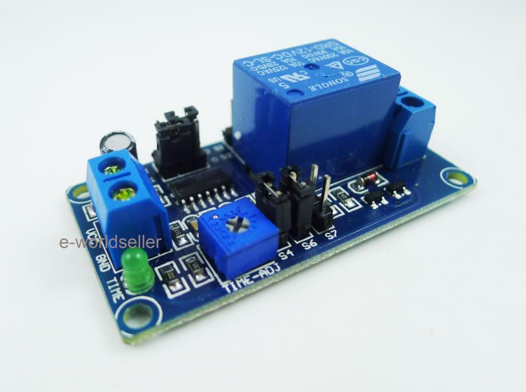
    The simple pulse idea may not be out the window, after all...

    http://www.ebay.com/itm/DC-12V-Delay...item27df53e098


    It's a digital 555 based system, but it's relayed, so the output is electromechanical.

    I've also found a slew of off delay relays and on delay relays that are simple 555 pcbs for cheaper that use small potentiometers. They could be used in place of this one, but the idea is what caught my attention.

    Oddly enough, I was shopping for a delay relay for a windshield wiper mod that I want to do on one of my old cars, that doesn't have a wiper delay.

    The off / on delay relays are about $7 each. They would require a little butchering. I'd want the pots more accessible, so I'd have to desolder the time adj pot and wire rotary pots in.

    http://www.ebay.com/itm/DC-12V-delay...tem3a87052f11\


    Two of those would be required, bounced off of each other to cycle. If I had a base signal that was always there, it would be on/ on with two different amp settings at the pedal.

  19. #19
    Join Date
    May 2012
    Location
    Disneyland
    Posts
    2,662

    Default

    What pulse frequency are you looking for anyway? Relays can only switch so fast, and you might also have to deal with contact bounce and such. An SSR could be swapped if you want, or you could just build the required circuit to switch directly.
    Long arc, short arc, heliarc and in-the-dark!

  20. Default

    Something in the 120hz range and lower.

    I know that relays are used for buzzers in alarm clocks with coils, etc, but I can see how consistency might be an issue beyond X frequency.

    I'm at a point with this where I think I'm going to keep it as simple as I can. I finally brought the welder inside to do some preliminary testing and I'm having a difficult time understanding which model I have and how it is supposed to display functions under trigger/ panel or pedal use.

Similar Threads

  1. New Tig Cart Design - tell me what you think
    By dawjr32223 in forum Other Custom Fabrications
    Replies: 16
    Last Post: 01-02-2013, 03:57 PM
  2. New cart design, am I nuts?
    By Trip59 in forum Other Custom Fabrications
    Replies: 15
    Last Post: 08-03-2012, 04:24 AM
  3. Possible design idea for HF gap issues
    By hooda in forum TIG Welding (GTAW/GTAW-P)
    Replies: 3
    Last Post: 01-10-2012, 03:58 AM

Posting Permissions

  • You may not post new threads
  • You may not post replies
  • You may not post attachments
  • You may not edit your posts
  •